1. Introduction
This document describes a file format (xml based) which can be used to define an airplane. It is easy to understand and write, but contains everything needed to create:
-
input files for AVL (.avl and .mass)
-
a 3D model of the airplane (without complex fuselage parts)
-
hard points/wheels for CRRCSim
2. Coordinate system
Coordinate system used in this file:
- x
-
positive forward
- y
-
positive towards right wing tip
- z
-
positive downwards
You don’t have to use the center of gravity as reference point (x=0, y=0, z=0). You can use any point you like. The following example uses the nose point of the wing’s root section.
3. General file format
The file basically uses xml syntax, which means that it is a simple ASCII file (every operating system offers at least one application to edit it: notepad, vi, emacs, …).
It can be structured hierarchically. You can write something like a group, with an opening and a closing tag, both having the same name:
<group1>
</group1>
Because it is a group, it can contain something else:
<group1>
  <group2>
  </group2>
  <group13>
  </group13>
</group1>
A group can have attributes, their order is not important:
<group1 attr1="42" attr2="13">
</group1>
If this group doesn’t contain something else, you can write it down somewhat shorter (without the closing tag):
<group1 attr1="42" attr2="13" />
Note the / at its end in this case.
Furthermore, the file format defines certain group and attribute names.
4. An example file
Let’s take a look at a simple example file: allegro_lite_2m.xml. It is part of
the zip archive on this page and can be found at
output/input/allegro_lite_2m.xml.
Everything shown in boxes like that
+--- allegro_lite_2m.xml --------------------------------
|
|
+--------------------------------------------------------
is part of this file. The leading " | " in every line is not a part of the file, of course.
The file starts with some header lines:
+--- allegro_lite_2m.xml --------------------------------
| <?xml version="1.0" ?>
| <data version="1">
+--------------------------------------------------------
4.1. Units
A section which describes units used in this file and units to use in output files:
+--- allegro_lite_2m.xml --------------------------------
|   <unit>
|     <!-- Units of input data in m, kg, s.
|          So if you want to input ft and slug:
|          length="0.3048" mass="14.5939041995"
|          -->
|     <input  length="0.0254" mass="0.001" time="1" />
|     <output length="0.0254" mass="0.001" time="1" />
|   </unit>
+--------------------------------------------------------
It contains a comment enclosed in <!-- -->. Comments like that are allowed
in the file.
The example states that lengths are in inch and masses in grams in the input file.
Output units are only used for AVL output; you can set them to whatever you like, it only affects data exchanged with AVL, but not data for CRRCSim or the 3D model.
For CRRCSim and 3D model, length is fixed to 1ft=0.3048m.
Hint: let’s assume you have a drawing of your plane with
l_p=1cm on drawing <-> l_r=10cm in reality
Set
length = 1mm*l_r/l_p = 0.01m
and write down coordinates in millimeters from the drawing. This method is especially useful if you have a drawing with some odd scale.
Scaling an airplane is easy this way, too (just don’t forget to change mass units as well).
4.2. Aerodynamic surfaces
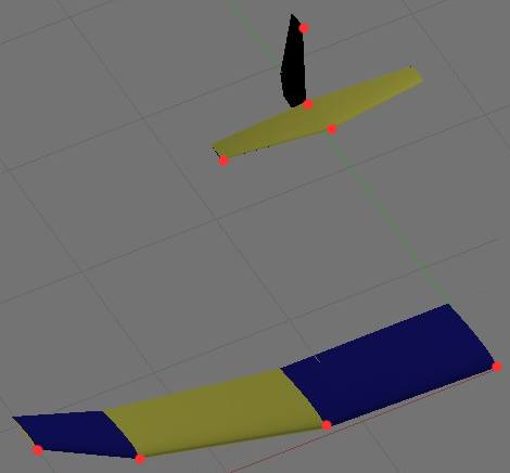
Every wing is divided into sections. Only the right half of the wing (y>0) is described; the left side is automatically created (of course this is not applicable to a rudder). The following picture shows the positions of the leading edge points to be written down (except the lower part of the rudder, which is not visible). One half of allegro’s main wing consists of three parts, so four leading edge points have to be defined.
Start of the part describing aerodynamic surfaces:
+--- allegro_lite_2m.xml --------------------------------
|   <surface>
+--------------------------------------------------------
The main wing:
+--- allegro_lite_2m.xml --------------------------------
|     <surface x="0" y="0" z="0" alpha="0">
|       <description>main wing</description>
+--------------------------------------------------------
x,y,z,alpha are offsets which are applied to every section of this surface (added to the values written in a section, see below). Just set those offsets to zero in order to use absolute values in every section.
The first section is the root chord; remember that its leading edge is used as the coordinate system’s reference point (x=y=z=0).
+--- allegro_lite_2m.xml --------------------------------
|       <sections>
|         <section x="0"      y="0"    z="0"    c="8"   alpha="1.49" airfoil="ag35" />
|         <section x="-0.5"   y="15"   z="0"    c="7.5" alpha="1.38" airfoil="ag36" >
|           <mass mass="78" />
|         </section>
|         <section x="-1.875" y="31"   z="-3.3" c="6"   alpha="1.22" airfoil="ag37" >
|           <mass mass="55.5" />
|         </section>
|         <section x="-3.625" y="39.3" z="-7"   c="4"   alpha="0.94" airfoil="ag38" >
|           <mass mass="12.0" />
|         </section>
|       </sections>
|     </surface>
+--------------------------------------------------------
x, y, z is the position of the leading edge point. c is the wing’s chord, alpha
the angle of incidence (in degrees; positive → leading edge up).
airfoil is the name of the airfoil in use, without path and suffix. Use
any airfoil name from
http://www.ae.uiuc.edu/m-selig/ads/coord_database.html
(currently version 2.0).
In the case shown above, the mass of every part of the wing is known. It is defined as the mass of one section to the previous section, therefore the first section has no mass.
If you only knew the mass of the whole wing, you would use:
+--- alternative ----------------------------------------
|     <surface x="0" y="0" z="0" alpha="0">
|       <description>main wing</description>
|       <mass mass="145.5" />
|       <sections>
|         <section x="0"      y="0"    z="0"    c="8"   alpha="1.49" airfoil="ag35" />
|         <section x="-0.5"   y="15"   z="0"    c="7.5" alpha="1.38" airfoil="ag36" />
|         <section x="-1.875" y="31"   z="-3.3" c="6"   alpha="1.22" airfoil="ag37" />
|         <section x="-3.625" y="39.3" z="-7"   c="4"   alpha="0.94" airfoil="ag38" />
|       </sections>
|     </surface>
+--------------------------------------------------------
145.5g is the mass of half the wing — just the part described here.
Instead of mass, you could also specify density in both cases. The mass will be
calculated using the volume of the wing.
+--- alternative ----------------------------------------
|       <mass density="9300" />
+--------------------------------------------------------
The elevator follows the same rules, but makes use of flaps. No airfoil is specified, so a default is used.
+--- allegro_lite_2m.xml --------------------------------
|     <surface x="-27.5" y="0" z="-1.25">
|       <mass mass="6" />
|       <description>horizontal stab</description>
|       <sections>
|         <section x="0"     y="0" z="0" c="3.5" flp="0.0">
|           <control name="elevator" />
|         </section>
|         <section x="-1.15" y="9" z="0" c="1.8" flp="0.0">
|           <control name="elevator" />
|         </section>
|       </sections>
|     </surface>
+--------------------------------------------------------
flp tells about the starting position of the trailing edge flap relative
to the chord length. Its starting position is c*flp relative to leading
edge, so flp="0" means that the whole wing rotates as a flap. The flap’s
length is c*(1-flp).
|
Note
|
This definition is not user friendly. Maybe using something like absolute_length_of_flap = `c` * `rel_flp_len` `flp` = 1 - `rel_flp_len` would be easier to understand. |
In this case the input variable is called elevator.
Here the offset feature is used — the section coordinates are relative to
the root chord leading edge (being at x=y=z=0) and offset by the values given at
surface.
The rudder is similar, but has a trailing edge flap starting at a relative
chord of 0.8.
Unlike main wing and elevator, it has an attribute dup="0" which means that
it is not mirrored at y=0.
naca0010 is the airfoil to be used. Here it is stated at surface. A
single section can override this default (notation: see main wing above).
+--- allegro_lite_2m.xml --------------------------------
|     <surface x="-33" dup="0" airfoil="naca0010">
|       <mass mass="10" />
|       <description>this is the rudder</description>
|       <sections>
|         <section x="1.28"   y="0" z="2"     c="3.2"   flp="0.8" >
|           <control name="rudder" />
|         </section>
|         <section x="1.68"   y="0" z="0"     c="4.2"   flp="0.8" >
|           <control name="rudder" />
|         </section>
|         <section x="1.5388" y="0" z="-1.25" c="3.847" flp="0.8" >
|           <control name="rudder" />
|         </section>
|         <section x="0.72"   y="0" z="-8.5"  c="1.8"   flp="0.8" >
|           <control name="rudder" />
|         </section>
|       </sections>
|     </surface>
+--------------------------------------------------------
End of aerodynamic surfaces:
+--- allegro_lite_2m.xml --------------------------------
|   </surface>
+--------------------------------------------------------
4.3. Control variables
We have used names of control variables for rudder and elevator deflections. Now we need to define their gain and direction:
+--- allegro_lite_2m.xml --------------------------------
|   <controls>
|     <control name="elevator" gain="20.0" sgndup="1" />
|     <control name="rudder"   gain="20.0" />
|   </controls>
+--------------------------------------------------------
Use sgndup="-1" for ailerons and rudder on a v-tail.
In this part of the file, gain has the meaning of a default value. It can
be overwritten in a section. One control can have different gains at any
section.
This value of gain is directly transferred to AVL, where it has the
meaning of "degrees deflection / control variable". In CRRCSim, the control
variable varies in the range of -0.5 .. 0.5, so a gain of 20 results in a
maximum deflection of +/- 10°.
4.4. Description of additional items
You can specify additional items with position and mass. They are not drawn in any way and are just used to calculate mass, center of gravity and inertia.
+--- allegro_lite_2m.xml --------------------------------
|   <mass>
|     <point>
|       <pos x="0" y="0" z="0" />
|       <mass mass="70" />
|       <description>fuselage pod</description>
|     </point>
|     <point>
|       <pos x="1" y="0" z="0" />
|       <mass mass="23" />
|       <description>RX</description>
|     </point>
|     <point>
|       <pos x="2.5" y="0" z="0" />
|       <mass mass="18" />
|       <description>servos</description>
|     </point>
|     <point>
|       <pos x="6" y="0" z="0" />
|       <mass mass="18" />
|       <description>nose wt.</description>
|     </point>
|     <point>
|       <pos x="4" y="0" z="0" />
|       <mass mass="57" />
|       <description>battery: will be used to adjust CG</description>
|     </point>
|   </mass>
+--------------------------------------------------------
A similar section is body which follows the same syntax as mass, but its
items are visible in 3D output:
+--- allegro_lite_2m.xml --------------------------------
|   <body>
|     <frustum>
|       <pos x="-5.5"  y="0" z="0" ri="0" ro="0.4" />
|       <pos x="-32.5" y="0" z="0" ri="0" ro="0.4" />
|       <mass mass="15" />
|       <description>boom+rods</description>
|       <vis material="black01" />
|     </frustum>
|   </body>
+--------------------------------------------------------
This frustum is defined by two points, which are the center points of the
circles describing it. They have an inner radius and an outer radius. The
inner radius is zero, so this is a solid body. As it has a volume, you can
define its density instead of its mass.
4.4.1. Drop
There is an item which currently is only used for 3D display (so you must
not define a mass) and looks like
a raindrop. You can use it to draw a fuselage pod, for example.
pos1 and pos2 describe positions of nose and tail. ri is the radius in
direction (pos_radius.x|pos_radius.y|pos_radius.z), ro is the radius
normal to this direction. If its profile is a circle, you don’t need to define
x, y, z and ro.
+--------------------------------------------------------
|     <drop sub_t="10" sub_r="16">
|       <pos1       x="6"   y="0" z="0.45"  />
|       <pos2       x="-11" y="0" z="0.45" />
|       <pos_radius x="0" y="0" z="1" ri="1" ro="0.85" />
|       <vis material="blue01" />
|       <description>fuselage pod</description>
|     </drop>
+--------------------------------------------------------
4.5. Constraints
If all the mass and geometry data in the file is really accurate, the real center of gravity will be calculated and used. If not, the result will be a wrong CG, which in turns results in garbage produced by AVL. That is not AVL’s fault!
If you want to, you can set a constraint to specify the position of the CG:
+--- allegro_lite_2m.xml --------------------------------
|   <constraints>
|     <CG x="-3.04" adjust="pos" />
|     <lift CL="0.62" />
|   </constraints>
+--------------------------------------------------------
+--- alternative ----------------------------------------
|   <constraints>
|     <CG x="-3.04" adjust="mass" />
|     <lift CL="0.62" />
|   </constraints>
+--------------------------------------------------------
The program will change position (first example) or mass (second example) of
a mass item to achieve this CG. To be able to do so, there must be an item
to play with: the last item in the mass section needs to have a mass
entry. The example (allegro_lite_2m.xml) above is valid and realistic in
this case, as the last item is the battery with a mass of 57 grams. Its
position or mass will be altered to achieve the CG’s position.
The constraint lift.CL specifies the lift at trimmed flight. If that one is
not given, the trim condition will be to achieve alpha=0.
4.6. End of file
+--- allegro_lite_2m.xml --------------------------------
| </data>
+--------------------------------------------------------
5. Things not mentioned in this example
5.1. Misc
-
The string inside of
<description> </description>can be anything and use multiple lines, too.
5.2. Flaps
The description of flaps is easy to understand as long as there is exactly one
flap along the whole wing: just add a control to every section.
Wing with three panels; aileron on middle panel:
+--- alternative ----------------------------------------
|     <surface x="0" y="0" z="0" alpha="0">
|       <description>wing</description>
|       <mass mass="78" />
|       <sections>
|         <section x="0"      y="0"    z="0"    c="8" />
|         <section x="-0.5"   y="15"   z="0"    c="7.5" flp="0.8" >
|           <control name="aileron" />
|         </section>
|         <section x="-1.875" y="31"   z="-3.3" c="6"   flp="0.8" >
|           <control name="aileron" />
|         </section>
|         <section x="-3.625" y="39.3" z="-7"   c="4" />
|       </sections>
|     </surface>
+--------------------------------------------------------
Same wing, but: camber on inner panel, aileron on middle panel. The
gain is explicitely stated for every control and section, overriding the
default value in the controls section.
+--- alternative ----------------------------------------
|     <surface x="0" y="0" z="0" alpha="0">
|       <description>wing</description>
|       <mass mass="78" />
|       <sections>
|         <section x="0"      y="0"    z="0"    c="8"   flp="0.8" >
|           <control name="camber"  gain="0.8" />
|         </section>
|         <section x="-0.5"   y="15"   z="0"    c="7.5" flp="0.8" >
|           <control name="camber"  gain="0.8" />
|           <control name="aileron" gain="1.0" />
|         </section>
|         <section x="-1.875" y="31"   z="-3.3" c="6"   flp="0.8" >
|           <control name="aileron" gain="1.0" />
|         </section>
|         <section x="-3.625" y="39.3" z="-7"   c="4" />
|       </sections>
|     </surface>
+--------------------------------------------------------
The same wing, but camber is mixed on aileron:
+--- alternative ----------------------------------------
|     <surface x="0" y="0" z="0" alpha="0">
|       <description>wing</description>
|       <mass mass="78" />
|       <sections>
|         <section x="0"      y="0"    z="0"    c="8"   flp="0.8" >
|           <control name="camber"  gain="0.8" />
|         </section>
|         <section x="-0.5"   y="15"   z="0"    c="7.5" flp="0.8" >
|           <control name="camber"  gain="0.8" />
|           <control name="aileron" gain="1.0" />
|         </section>
|         <section x="-1.875" y="31"   z="-3.3" c="6"   flp="0.8" >
|           <control name="camber"  gain="0.3" />
|           <control name="aileron" gain="1.0" />
|         </section>
|         <section x="-3.625" y="39.3" z="-7"   c="4" />
|       </sections>
|     </surface>
+--------------------------------------------------------
Be careful: this definition results in something you don’t want to have. The
flap on the middle panel moves correctly as far as aileron is concerned, but
it becomes a flexible-surface control system for camber. Its angle of
deflection is not equal at the second and third section (gain is
different).
On a real wing you might have this:
+--- alternative ----------------------------------------
|     <surface x="0" y="0" z="0" alpha="0">
|       <description>wing</description>
|       <mass mass="78" />
|       <sections>
|         <section x="0"      y="0"    z="0"    c="8"   flp="0.75" >
|           <control name="camber"  gain="0.8" />
|         </section>
|         <section x="-0.5"   y="15"   z="0"    c="7.5" flpp="0.75" flpn="0.8" >
|           <control name="camber"  gainp="0.8" gainn="0.3" />
|           <control name="aileron" gainn="1.0" />
|         </section>
|         <section x="-1.875" y="31"   z="-3.3" c="6"   flp="0.8" >
|           <control name="camber"  gain="0.3" />
|           <control name="aileron" gain="1.0" />
|         </section>
|         <section x="-3.625" y="39.3" z="-7"   c="4" />
|       </sections>
|     </surface>
+--------------------------------------------------------
The section which separates inner and outer flap has flpp,flpn instead of
flp, as both flaps have different sizes (flpp to previous section and flpn
to next section). The same holds for gain of camber at this section.
aileron only controls the outer flap, so it does not have an entry gainp.
5.3. Assumptions
You can add a list of assumptions.
+--- alternative ----------------------------------------
|   <assumptions>
|     <drag>
|       <profile CDp_default="0.02" />
|     </drag>
|     <misc span_eff="0.95" />
|   </assumptions>
+--------------------------------------------------------
- Name
-
assumptions.drag.profile.CDp_default - Required
-
no (defaults to 0.02)
- Use
-
is written to .avl as
CDp(see avl manual). - Name
-
assumptions.misc.span_eff - Required
-
no (defaults to 0.95)
- Use
-
is written to .xml as
aero.misc.span_eff. A old comment in CRRCSim says: 0.95 for most planes, 0.85 flying wing.
6. More input features
6.1. Center of gravity
Instead of constraints.CG.x you may also specify the stability
margin constraints.CG.stm.
Instead letting the CG be adjusted by changing an items position
(constraints.CG.adjust="pos") you may also achieve its adjustment by
changing its mass (constraints.CG.adjust="mass").
6.2. Interpolation of section data
In case you need to define multiple sections for one wing and a parameter follows a linear equation along the wing’s y coordinate, you may leave that parameter out in the intermediate sections. You need to define it on the outer sections, though.
This is possible for x, z, c, alpha.
7. How to check your input file for correctness
Open your file with Mozilla, Firefox or Internet Explorer. If the browser does not display an error message, the file is correct as far as basic xml syntax is concerned.
8. History
-
Initial version.
-
Different boxes for contents of
allegro_lite_2m.xmland alternative notations. -
note about coordinate system origin
-
examples for flap configurations
-
more notes about units
-
assumptions
-
constraints
-
control gain: unit explanation
-
CL constraint
-
Jan Reucker pointed out some minor errors/things not quite clear in this document. Corrected.
-
Some additions to make it easier to understand.
-
More features explained
-
changed behaviour without
constraints.lift.CL
-
some data can be automatically interpolated on sections